
In the Steel Joints add-on, you can design connections according to the American standard ANSI/AISC 360‑16. The following design procedures are integrated:
- Load and Resistance Factor Design (LRFD)
- Allowable Stress Design (ASD)

- For the design according to Eurocode 3, the parameters of the National Annexes (NA) are integrated for the following countries:
-
 DIN EN 1993-1-1/NA:2016-04 (Germany)
 -
 ÖNORM EN 1993-1-1/NA:2015-12 (Austria)
 -
 SN EN 1993-1-1/NA:2016-07 (Switzerland)
 -
 BDS EN 1993-1-1/NA:2015-10 (Bulgaria)
 -
 BS EN 1993-1-1/NA:2016-07 (United Kingdom)
 -
 CEN EN 1993-1-1/2015-06 (European Union)
 -
 CYS EN 1993-1-1/NA:2015-07 (Cyprus)
 -
 CZE EN 1993-1-1/NA:2016-06 (Czech Republic)
 -
 DS EN 1993-1-1/NA:2015-07 (Denmark)
 -
 ELOT EN 1993-1-1/NA:2017-01 (Greece)
 -
 EVS EN 1993-1-1/NA:2015-08 (Estonia)
 -
 HRN EN 1993-1-1/NA:2016-03 (Croatia)
 -
 I S. EN 1993-1-1/NA:2016-03 (Ireland)
 -
 ILNAS EN 1993-1-1/NA:2015-06 (Luxembourg)
 -
 IST EN 1993-1-1/NA:2015-11 (Iceland)
 -
 LST EN 1993-1-1/NA:2017-01 (Lithuania)
 -
 LVS EN 1993-1-1/NA:2015-10 (Latvia)
 -
 MS EN 1993-1-1/NA:2010-01 (Malaysia)
 -
 MSZ EN 1993-1-1/NA:2015-11 (Hungary)
 -
 NBN EN 1993-1-1/NA:2015-07 (Belgium)
 -
 NEN EN 1993-1-1/NA:2016-12 (Netherlands)
 -
 NF EN 1993-1-1/NA:2016-02 (France)
 -
 NP EN 1993-1-1/NA:2009-03 (Portugal)
 -
 NS EN 1993-1-1/NA:2015-09 (Norway)
 -
 PN EN 1993-1-1/NA:2015-08 (Poland)
 -
 SFS EN 1993-1-1/NA:2015-08 (Finland)
 -
 SIST EN 1993-1-1/NA:2016-09 (Slovenia)
 -
 SR EN 1993-1-1/NA:2016-04 (Romania)
 -
 SS EN 1993-1-1/NA:2019-05 (Singapore)
 -
 SS EN 1993-1-1/NA:2015-06 (Sweden)
 -
 STN EN 1993-1-1/NA:2015-10 (Slovakia)
 -
 TKP EN 1993-1-1/NA:2015-04 (Belarus)
 -
 UNE EN 1993-1-1/NA:2016-02 (Spain)
 -
 UNI EN 1993-1-1/NA:2015-08 (Italy)
-
- The design according to US standard AISC 360 includes analysis methods according to:
-
 Load and Resistance Factor Design (LRFD)
 -
Allowable Stress Design (ASD)
-
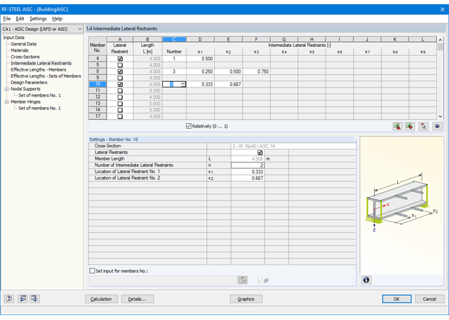
First, it is necessary to decide whether to perform design according to ASD or LRFD. Then, you can enter the load cases, load combinations, and result combinations to be designed. Load combinations according to ASCE 7 can be generated either manually or automatically in RFEM/RSTAB.
In the next steps, you can adjust presettings of lateral intermediate supports, effective lengths, and other standard-specific design parameters, such as the modification factor Cb for lateral-torsional buckling or the shear lag factor. In the case of continuous members, it is possible to define individual support conditions and eccentricities of each intermediate node of single members. A special FEA tool determines critical loads and moments required for the stability analysis.
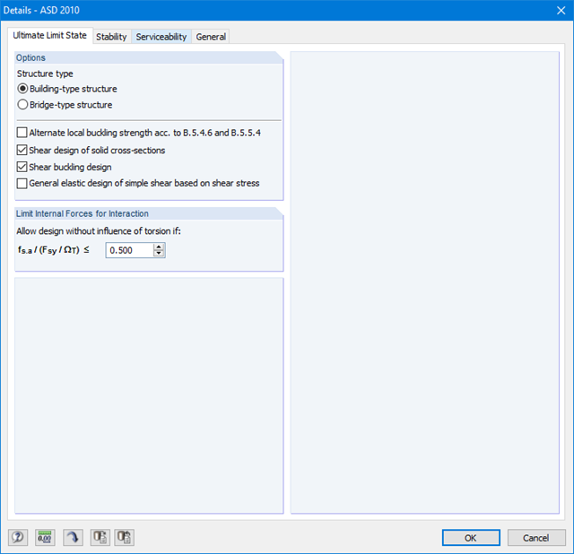
In connection with RFEM/RSTAB, it is possible to apply the Direct Analysis Method taking into account the influence of the general calculation according to the second-order analysis. In this way, you avoid using special enlargement factors.
First, it is necessary to decide whether to perform design according to ASD or LRFD. Then, you can enter the load cases, load combinations, and result combinations to be designed. Load combinations according to ASCE 7 can be generated either manually or automatically in RFEM/RSTAB.
Further specifications include presetting of lateral intermediate supports, effective lengths, and other standard-specific design parameters. When using continuous members, it is possible to define individual support conditions and eccentricities at each intermediate node of the single members. A special FEA tool then internally determines the effective radii of gyration required for the stability analysis for these situations.
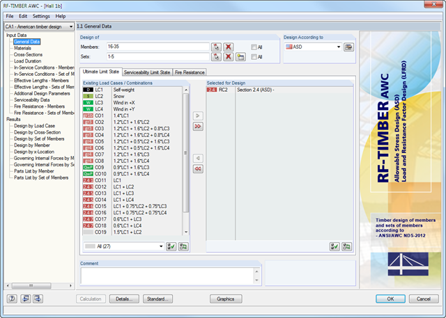
After opening the add‑on module, it is necessary to select the members/sets of members, load cases, load or result combinations for the ultimate limit state, serviceability limit state, and fire resistance design (only ASD). Also, you can select the design method (ASD or LRFD). The materials from RFEM/RSTAB are preset and can be adjusted in RF-/TIMBER AWC. Material properties listed in the respective standard are included in the material library.
When checking the cross-sections, you can specify whether to apply the design values of the relevant standard, or user-defined values. Then, you can consider the load duration classes (LDC), temperature effects, and moisture service conditions.
The deformation analysis requires the reference lengths of the relevant members and sets of members. Furthermore, you can define a specific direction of deflection, precamber and the beam type.
For fire resistance design, you can define the charring sides of a member or set of members.
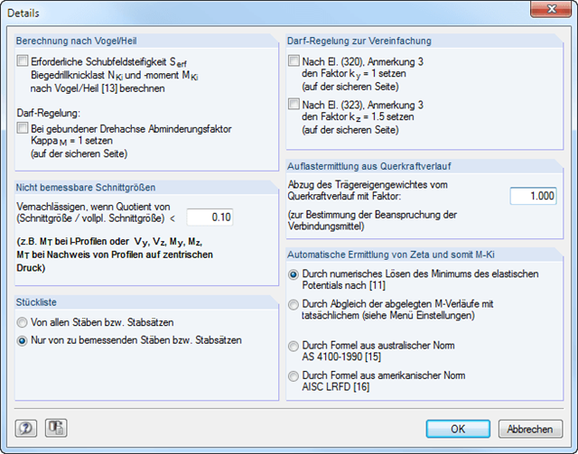
In RF‑/LTB, the design is usually performed according to the equivalent member method according to DIN 18800, Part 2. However, you can specify extensive detailed settings for the design in a separate dialog box:
Design according to Bird/Heil
Optionally, it is possible to apply the method according to Bird/Heil in the program
- the required shear stiffness Sreq
- the lateral-torsional buckling load Nki
- the critical buckling moment Mki
.
This plastic-plastic calculation method is only valid for lateral and torsional restraints with simple bending with simultaneous load introduction on the upper flange. Further requirements that must be met can be found in the program manual. In case of invalid conditions (for example, biaxial bending), RF-/LTB displays the corresponding error message. In addition, the reduction factorκM for the bending moments My can be set to 1.0 if a restrained rotation axis is present.
Non-Designable Internal Forces
It is possible to neglect non-designable internal forces and thus exclude them from the design if the quotient of the internal force and the fully plastic internal force falls below a certain value. This way, you can neglect, for example, a small moment about the minor axis, thus avoiding the method for biaxial bending.
Allowance according to DIN 18800, Part 2, Element (320) and Element (323)
Automatic determination of ζ
If you want the factor for the determination of the ideal elastic critical moment Mcr to be determined automatically, you can select one of the following types:
- Solving the elastic potential numerically
- Comparison of moment diagrams
- Australian Standard AS 4100-1990
- US standard AISC LRFD
When aligning the moment distributions, you can use the library which contains more than 600 moment distributions in tables.